
Board-level thermal design, local heatsink assessment and heat-spreading analysis for compact electronic assemblies.
Overview
This case study presents board-level thermal management and electronics cooling work for an electronic assembly containing multiple heat-generating components, local heatsinks and a supporting PCB structure. The work focused on identifying thermal hotspots, evaluating heatsink performance and understanding heat-spreading paths through the board and surrounding mechanical architecture.
Engineering Challenge
Electronic assemblies with dense component layouts can develop localised hotspots, uneven temperature gradients and limited heat-rejection paths. The design challenge was to understand how heat moved from individual components into local heatsinks, through the PCB structure and into the surrounding assembly, so that practical cooling and packaging decisions could be made early in the design process.
Engineering Scope
- Thermal analysis of PCB-mounted electronic components and local heat sources.
- Evaluation of local heatsink behaviour and heat-spreading effectiveness.
- Assessment of top-side and underside temperature distributions through the PCB structure.
- Identification of component hotspots, local temperature gradients and critical thermal paths.
- Support for electronics packaging and cooling design decisions within a compact assembly.
Top-Side Component and Heatsink Behaviour
Top-side thermal results were used to assess hotspot formation around heat-generating components and to evaluate the effectiveness of the local heatsink arrangement. This helped identify where heat was being concentrated and how effectively it was being spread away from critical components.
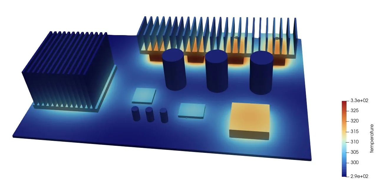
Top-side thermal distribution showing component hotspot behaviour and local heatsink performance.
PCB Heat-Spreading Assessment
Underside thermal results were used to examine the heat footprint through the PCB and identify how heat was spreading across the board structure. This provided additional understanding of thermal paths away from the component side and helped assess the contribution of the PCB to overall heat dissipation.

Underside thermal footprint illustrating heat spreading through the PCB structure.
Airflow CFD and Conjugate Heat Transfer
The thermal model was extended to include airflow CFD around the electronic assembly and local heatsinks. This allows airflow distribution, recirculation behaviour and local cooling effectiveness to be assessed together with board-level hotspot formation and heat spreading through the PCB.
The CFD model also supports design optimisation of heatsink orientation, fan inlet positioning and airflow paths within the enclosure. This is useful when comparing different component layouts, vertical or horizontal heatsink arrangements, and the effect of forced-air cooling on local component temperatures.
The combined thermal and flow model provides a more realistic view of how the electronics assembly performs inside an enclosure or forced-air cooling environment, supporting practical packaging, heatsink and airflow-path decisions during early design development.

CFD airflow and thermal visualisation of an electronics enclosure, showing velocity magnitude, flow paths over PCB-mounted components and the effect of heatsink orientation and fan inlet positioning.
Thermo-Mechanical Extension
Where required, the thermal model can be coupled to structural analysis to assess thermally induced deformation and mechanical stresses. This approach can be used to evaluate PCB distortion, component loading, mounting constraints and reliability risks caused by temperature gradients.
Outcome
- Demonstrated board-level electronics thermal simulation and cooling-assessment capability.
- Evaluated local heatsink effectiveness and heat-spreading behaviour through the PCB structure.
- Identified critical component hotspots, local gradients and relevant thermal paths.
- Supported practical thermal design decisions for electronic assemblies and compact product architectures.
- Extended the workflow to include airflow CFD for enclosure airflow, heatsink orientation and fan inlet positioning.
- Established a workflow that can be extended to coupled thermo-mechanical assessment where reliability or distortion risks are important.
Confidentiality Note
This case study is intentionally described at a high level. No confidential circuit details, component specifications, proprietary design data, internal client documentation or restricted project information are disclosed.